
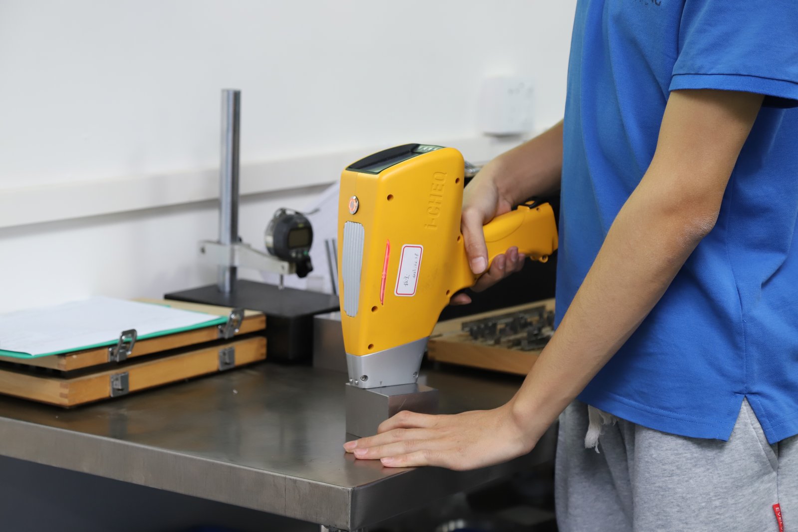
Precision machining parts are defined by relationships, and relationships need an origin. The tolerance on a bore means little until it is measured against the face or axis that locates it; the finish on a sealing face means little until the surface can be reached and read; and a drawing full of tight callouts can still fail if its callouts do not share a common, physical, controllable datum. This guide argues that the datum structure is the organizing principle of a precision drawing: it decides what can be held, how features are measured, where finishes are reachable, and why some parts inspect cleanly while others argue at the CMM.
Why does the datum structure decide what a precision part can hold?
Every geometric callout is a statement about a relationship, and every relationship is measured from an origin. On a machined part that origin is the datum: the physical feature the inspector uses to build the coordinate system in which everything else is measured. If the datum is clear, machined and accessible, the measurement is stable and repeatable, and the tolerance means the same thing to the shop, the inspector and your receiving team. If the datum is ambiguous — buried in a feature the process cannot control, or chosen differently by the programmer and the inspector — the measurement drifts, and the tolerance becomes a matter of who measured it rather than what the part is.
The datum choice therefore decides what the process must protect. Features referenced to a datum that is cut early and held stable can be produced and measured in one consistent frame; features whose datum is chosen after the fact inherit whatever frame the inspector happens to build. A precision part with a well-chosen datum structure is a part whose geometry is decided by the machining; one with a neglected datum structure is a part whose geometry is decided by the measurement, which is the opposite of what a drawing should do.
Which surfaces make good datums on a machined part?
A good datum is machined, accessible, large enough for the measurement to anchor, and functionally meaningful. On rotational work the turned axis or a datum diameter serves the concentricity and run-out story. On prismatic work a milled face, machined flat and square, serves the position and perpendicularity story. A bore that locates the part in its assembly is a natural datum for the features that must sit around it. Each of these is a feature the process can hold and the CMM can probe consistently, which is the practical definition of a datum that will not cause arguments.
The features that make poor datums are equally recognizable. A datum chosen on a soft, secondary surface that was never machined flat anchors the measurement on something the process does not control. A datum on a feature too small for the probe to seat reliably makes the measurement repeat poorly. A datum that is functionally irrelevant makes the whole frame elegant but wrong, because the features that matter in the assembly are not the ones the drawing references. The datum list on a drawing should read like the assembly's functional logic: the features that locate the part in its application are the features everything else is measured from.
How should tolerance and finish callouts be organized on a precision drawing?
The organization that serves precision best is the datum story: identify the functional datum, make sure the process cuts it early and holds it stable, and reference every critical feature to it. The tolerance and the finish belong on the same line for each critical feature, because they are produced together and verified together — the bore at its diameter band with the finish that lets the CMM probe it, the sealing face at its finish with the tolerance of the surface it sits on. Features that hang off the same datum inspect in one frame, and features that would need a second frame are exactly the ones the review should question.
The discipline of the datum story also controls cost, because precision is cheaper when it is organized. A drawing whose critical features share a small number of datums produces a short, unambiguous inspection plan, and a short inspection plan is a fast one. A drawing whose tight callouts are scattered across unrelated datums multiplies the measurement frames, the CMM programs and the arguments about which frame each feature belongs to. The datum-led drawing is not stricter than the scatter; it is cheaper and clearer, because it measures each feature once, against the origin the assembly actually uses.
What do tolerance and finish each do to the inspection plan?
Every tight tolerance adds a measurement against its datum, and every finish callout adds a surface reading on its feature, so the drawing's callout list is a preview of the inspection plan. A part with a short list of datum-referenced critical features produces a plan that runs quickly and reports cleanly: build the frame, measure the few features, read the finishes, done. A part with many tight callouts scattered across unrelated frames produces a plan that runs long, reports a stack of values that are hard to reconcile, and generates the disagreements that precision programs are famous for, not because the parts are bad, but because the drawing never said which frame each feature belonged to.
The finish callouts shape the plan in the same way. A finish on a feature that is also a datum is read as part of the frame, because the probe seats better on a controlled surface. A finish on a sealing face is read with the surface instrument when that face is reached. A finish on a face nothing measures is a reading that produces a number nobody uses. When the finish callouts follow the functional features, every finish reading lands on a surface that matters; when they are scattered, the inspection spends time reading surfaces the assembly never touches.
How do I know if a feature is over-toleranced relative to its datum?
The test is whether the measurement can actually resolve the claim. A position callout against a datum that is itself unstable is a claim the process cannot hold twice in a row. A fine finish on a face whose only measurement anchor is a soft edge is a claim the instrument cannot reproduce. A concentricity between two features cut in different setups is a claim that depends on the transfer as much as on the machine. In each case the callout is over-toleranced relative to its datum, because the datum or the process cannot support the measurement the callout demands — however precisely the number was written.
The DFM review is where this test gets run, and the question to ask of every tight callout is not whether the number is achievable in theory but whether it is provable in practice. A feature that can be machined to the number but not measured to it is a feature that will fail at the first article regardless of the machining, because the inspection cannot confirm what the drawing claims. Precision callouts that survive the review are the ones whose datum, process and measurement all agree; the ones that fail are the ones that looked impressive on paper and were never anchored to anything the floor could hold.
The same provability test applies to the finish callouts, where the question is whether the instrument can reach and read the surface the drawing specifies. A finish on a narrow groove that no stylus can enter, or on a face hidden behind a wall that no probe can reach, is a callout that cannot be verified no matter how carefully the pass was run. The review should flag such callouts and propose either an instrumented process that can measure them — a non-contact surface instrument where a stylus cannot go — or a re-designed feature that brings the surface to a measurable location. A finish that cannot be read is a finish that will be argued about, and the argument is cheapest when it happens at the drawing stage rather than at the first article.
What finishes pair naturally with datum-referenced features?
The finish follows the function and the process, and on a datum-led drawing the pairing is natural. The locating face that doubles as the datum carries a controlled finish because it is machined late, held flat and used to anchor everything else — its finish is part of the measurement story as much as the geometry story. A sealing face carries its Ra together with the tolerance of its surface, because the pass that holds the size produces the finish. A datum bore carries the finish that lets the CMM probe it consistently, because a rough bore seats the probe less predictably than a controlled one. In each case the finish is not decoration; it is part of what makes the feature measurable.
Writing the finish on the same line as the tolerance tells the shop that the two are one requirement, produced by one pass and verified in one reading. A sealing face whose Ra is called on the same line as its size will be finished and measured as a unit; one whose Ra is buried in a general note will be finished to whatever the last pass left and discovered at the first article. On a precision part the finish and the tolerance are two views of the same feature, and the drawing that treats them as one specification is the drawing whose first article can be approved without a debate.
How should the first article verify a datum-led drawing?
The first article should be measured the way the drawing is organized: establish the datums first, building the coordinate frame from the features the drawing named, then verify the critical features against that frame, then read the finishes on the faces called out. A report organized by the datum story is a report you can read without re-deriving the drawing; it answers, feature by feature, what was measured, against which datum, and with what value. A report that verifies features against whatever frame was convenient is a report that hides the datum story, and a hidden datum story is a tolerance dispute waiting to happen.
The first article is also where the datum choice gets its real test. If the datum features measure cleanly and the frame builds without interpretation, the drawing's structure is sound and the production lot can ride the same frame. If the datum features drift or the frame has to be improvised, the drawing's structure has a problem that no amount of tolerance tightening will fix. The quality page on this site explains how datum-based measurement is handled, and the services page covers the processes a precision route can carry. A precision part whose callouts follow its datums, whose finishes pair with its functions, and whose first article is measured the way its drawing is organized is a part whose precision is provable rather than promised.
The datum-led discipline pays its largest dividend on repeat orders, because a datum structure that was validated on the first article becomes the standing measurement plan for every later lot. The CMM program, the fixture orientation and the finish readings are all anchored to the same datums, so the second lot measures the way the first did and the report reads the way the first was read. A part whose datum story was settled once stops costing measurement debates on every reorder; one whose datums were never settled restarts the arguments each time the part is made. In precision machining, a stable datum structure is the quietest cost saver on the drawing, because it is the one that makes every inspection after the first one cheap and every report after the first one readable.
Frequently Asked Questions
Why does the datum structure decide what a precision part can hold?
Because every geometric callout is measured from a datum, where the measurement builds its coordinate system. A part with clear, physical datums measures the same way every time; one with ambiguous datums produces measurements that drift between inspectors whatever the drawing promised.
Which surfaces make good datums on a machined part?
Surfaces that are machined, accessible, large enough for the measurement to anchor, and functionally meaningful: a turned axis, a milled face, a locating bore. A datum cut early and used by every later feature ties the geometry together; a soft secondary datum ties nothing.
How should tolerance and finish callouts be organized on a precision drawing?
Around the datum story: identify the functional datum, cut it first, and reference every critical feature to it with tolerance and finish on the same line. Features sharing a datum inspect in one frame, and features needing a second frame are the ones to question.
What do tolerance and finish each do to the inspection plan?
Every tight tolerance adds a measurement against its datum, and every finish callout adds a surface reading. A short list of datum-referenced critical features produces a short, unambiguous plan; scattered tight callouts produce a long plan full of arguments about which frame each feature belongs to.
How do I know if a feature is over-toleranced relative to its datum?
Ask whether the measurement can resolve the claim. A tight callout against an unstable datum, or a fine finish anchored on a soft edge, cannot be reproduced, so it is over-toleranced however confidently it was written. The review should test provability, not just achievability.
What finishes pair naturally with datum-referenced features?
The finish follows function and process: a locating datum face carries a controlled finish, a sealing face carries its Ra with its size, and a datum bore carries the finish that lets the CMM probe it consistently. The finish belongs on the line with the tolerance, measured in the same frame.
How should the first article verify a datum-led drawing?
Establish the datums first, build the coordinate frame, verify the critical features against it, and read the finishes on the called-out faces. A report organized like the drawing is readable; one that verifies against a convenient frame hides the datum story.
Want your datum structure read before your tolerances are priced?
Email the STEP or IGES model with your toleranced drawing to [email protected] or call +86 13126536955, and receive a DFM review that names the functional datums, the features that belong to each, and the callouts that cannot be proven against their own frame.